What Are Circuit Breaker Parts and How Do They Work?
Electricity rarely announces danger before damage begins. A loose terminal may heat quietly, while a short circuit can release intense energy within milliseconds. Circuit Breaker Parts exist to control that risk. They detect abnormal current, interrupt the circuit, and help prevent damaged conductors, fires, and equipment failure.
The International Energy Agency’s Electricity 2024 report forecasts global electricity demand will grow by about 4% annually through 2026. More demand means greater pressure on distribution networks, industrial panels, data centers, and renewable-energy systems. Reliable protection therefore depends on more than selecting the correct breaker rating. Contacts, trip units, arc chutes, operating mechanisms, terminals, and insulating enclosures must work together. IEC 60947-2 and IEC 62271 provide important performance and testing frameworks for low-voltage and high-voltage equipment.
Small parts matter.
John Drengenberg, former Consumer Safety Director at UL, explains the practical purpose clearly: “Circuit breakers are designed to protect the wiring in your home from overheating.” That protection begins with the trip mechanism, but it does not end there. A worn contact can increase resistance. A weak spring can delay opening. Poorly tightened terminals can create hot spots that inspection cameras reveal before failure.
This guide examines how Circuit Breaker Parts function under overloads, short circuits, and routine switching. It also connects manufacturer specifications with field experience and industry data, including market analysis from MarketsandMarkets’ Circuit Breaker Market report. Some explanations may appear simple. The hardware is not. Even experienced technicians can overlook heat, vibration, aging, or installation conditions. That is where careful inspection becomes essential.
Circuit Breaker Basics: Purpose, Function, and Main Applications
Circuit breakers protect electrical systems by interrupting current when conditions become unsafe. Their main purpose is to limit damage from overloads and short circuits. An overload may heat a cable gradually, while a short circuit can create a dangerous surge within milliseconds. The breaker senses this change and opens the circuit. That action protects wiring, equipment, and people from excessive heat or electrical faults.
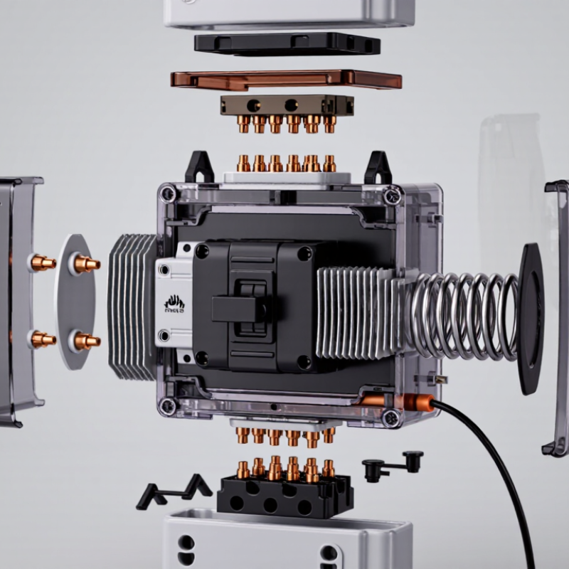
Inside the housing, several parts work together. Fixed and moving contacts carry current during normal operation. A trip mechanism separates them when protection is required. Thermal elements respond to prolonged overloads, while magnetic elements react quickly to severe faults. Some modern breakers use electronic sensors for more precise measurements. An arc chute helps control the spark created when contacts separate. Small parts matter. Without them, safe interruption is impossible.
Circuit breakers serve homes, offices, factories, transport systems, and renewable-energy installations. A household unit may protect a lighting circuit, while an industrial breaker can manage large motors and distribution panels. Selection depends on voltage, current rating, interrupting capacity, and fault conditions. Correct coordination allows the nearest breaker to trip first, reducing unnecessary shutdowns. Regular inspection can reveal loose terminals, heat marks, or repeated trips. The label alone may not show the whole risk. Installation conditions, aging, and maintenance history also matter. A basic explanation is useful, but real systems deserve careful testing by qualified professionals.
Essential Circuit Breaker Parts and Their Individual Roles
A circuit breaker combines several parts to detect faults and interrupt current safely. The molded frame supports the internal components and provides insulation around energized sections. Line and load terminals connect the breaker to incoming and outgoing conductors. Tight, clean connections matter. A loose terminal can create heat before the breaker detects a fault.
The operating mechanism moves the contacts between open and closed positions. Fixed and moving contacts normally carry current with low resistance. During a fault, they separate quickly and create an electrical arc. The arc chute divides and cools that arc, helping extinguish it inside the breaker. This small chamber does demanding work. Dust, wear, or damaged plates can reduce its performance.
The trip unit controls automatic opening. A thermal element responds to prolonged overloads, while a magnetic element reacts to high fault current almost instantly. Some breakers use electronic sensing for adjustable protection and clearer monitoring. Auxiliary contacts can report whether the breaker is open or closed. In practical panel inspections, technicians check terminal torque, contact wear, insulation condition, and trip operation. Visual checks are useful, but they cannot prove every internal part works correctly. That limitation is easy to overlook. A breaker may look clean while its mechanism moves slowly or its trip settings no longer match the circuit design. Proper testing and qualified evaluation remain essential.
How a Circuit Breaker Detects and Interrupts Fault Currents
What Are Circuit Breaker Parts and How Do They Work?
How a Circuit Breaker Detects and Interrupts Fault Currents
A circuit breaker uses several coordinated parts to detect dangerous current and stop it. The sensing element may be thermal, magnetic, electronic, or a combination of these methods. A thermal element responds to prolonged overloads by bending as heat increases. A magnetic element reacts almost instantly when a short circuit creates a sharp current surge. Electronic trip units measure current continuously and compare it with preset limits. Small differences matter.
Once the trip mechanism operates, the contacts separate quickly. Current does not stop quietly, however. An electric arc forms between the opening contacts. Arc chutes divide, cool, and lengthen this arc until it can no longer conduct. Springs provide the force needed for rapid contact movement. In practical inspections, technicians often check contact wear, mechanical movement, and signs of overheating. A breaker can look clean while its internal mechanism becomes unreliable. That detail deserves attention.
Tips: Match the breaker’s rating to the circuit design, conductor size, and expected fault level. Test protective devices according to qualified procedures, not casual guesses. Keep records of trip settings and inspection dates. Never assume a reset breaker has solved the cause. A repeated trip may indicate damaged insulation, loose connections, or excessive load. Even experienced people can misread a fault, so measured testing remains essential.
The Step-by-Step Process of Circuit Breaker Operation
A circuit breaker combines fixed and moving contacts, a trip unit, an operating mechanism, and an arc chute. These parts work together to control current safely. When the circuit operates normally, contacts remain closed and electricity travels through the terminals. The handle shows the breaker’s position, but it does not explain every internal action.
The process begins when excessive current creates heat or magnetic force inside the trip unit. A thermal element responds gradually to sustained overloads. A magnetic element reacts almost instantly to a severe short circuit. The trip unit releases the mechanism, and a spring drives the moving contact away from the fixed contact. An arc may appear between them. The arc chute divides, cools, and weakens this electrical path. Current then stops flowing through the protected circuit. The breaker can be reset only after the fault is identified and corrected.
The sequence sounds clean on paper. Real faults are often less predictable. Moisture, loose terminals, aging insulation, or repeated trips can change the response. Tips: Always isolate the supply and verify zero voltage before inspection. Use the correct rating for the circuit. Never force a handle back into position. Check for heat marks, unusual odors, or damaged insulation. A qualified electrician should test unclear conditions, because a visual check can miss internal damage. Manufacturer instructions and local electrical codes should guide installation and maintenance.
What Are Circuit Breaker Parts and How Do They Work?
This step waveform shows the logical operating sequence of a circuit breaker. During normal operation, the contacts remain closed and current flows. When an overload or short circuit is detected, the trip unit releases the latch, the operating mechanism separates the contacts, and the arc-extinguishing system interrupts the current. The breaker then remains open until it is safely reset.
The chart uses binary states: 1 means active or closed, while 0 means inactive or open. Actual interruption time depends on the breaker design, fault current, and applicable safety standard.