
Why Choose a Welded Ball Valve for Global Projects?
Global infrastructure projects demand more than a valve that simply opens and closes. They require dependable sealing, stable performance, and practical installation under difficult conditions. A Welded Ball Valve offers a compact, durable solution for pipelines carrying water, gas, oil, and industrial fluids. Its welded body removes many potential leakage paths around bolted connections. That matters beside a remote compressor station, where repair access may require hours of travel.
Valve engineering specialist Dr. John M. Campbell once stated, “A valve’s value is measured by its performance when access, time, and conditions are against it.” This principle explains why project engineers often consider welded construction for buried or high-pressure systems. A properly designed Welded Ball Valve can reduce maintenance points, tolerate vibration, and support long service intervals. However, welded does not automatically mean superior. Material selection, welding quality, non-destructive testing, coating systems, and pressure verification remain decisive.
Small details matter.
In my experience reviewing industrial specifications, teams sometimes focus too heavily on purchase price. They overlook actuation space, drainage, field welding procedures, and spare-part availability. That is an uncomfortable weakness. Global projects also face different climates, transport routes, and technical standards. Therefore, valve selection should combine manufacturer capability, documented testing, traceable materials, and application-specific engineering. A reliable Welded Ball Valve is not merely a product choice. It is a risk-control decision shaped by evidence, workmanship, and honest evaluation.
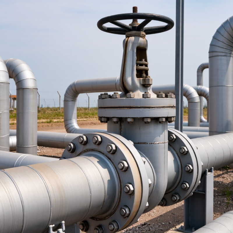
A welded ball valve has a valve body permanently joined to the pipeline by welding. Unlike flanged designs, it uses no detachable bolts at the connection points. Inside, a drilled metal ball rotates around a fixed stem. A 90-degree turn aligns the bore with the pipe for full flow. Another quarter-turn places the solid ball across the passage and stops flow. Simple motion. Reliable isolation.
This design suits buried pipelines, terminals, and high-pressure transmission systems. Its compact body reduces external leakage paths and supports stable operation during temperature changes. Grand View Research estimated the global industrial valves market at USD 74.7 billion in 2022, showing the scale of infrastructure requiring dependable flow control. The International Energy Agency also reported over USD 3 trillion in global energy investment for 2024. More projects mean more attention to valve integrity.
Engineering teams normally assess welded valves against standards such as API 6D and ASME B16.34. Qualified welding procedures, dimensional alignment, pressure testing, and non-destructive examination remain essential. Field commissioning often exposes a practical weakness: a welded valve is difficult to remove after installation. Poor pipe alignment can also stress the body and shorten seat life. That trade-off deserves honesty. A welded connection reduces leakage risks, but it can complicate future maintenance. Good specifications should define inspection access, actuator orientation, isolation requirements, and repair planning before welding begins.
Why Choose a Welded Ball Valve for Global Projects?
Global pipeline projects face changing temperatures, soil movement, and uneven maintenance access. A welded ball valve removes many flange joints, reducing external leak paths and installation points. Its compact body also fits narrow valve chambers and buried pipeline sections. Built for permanence. Not maintenance-free.
Design details matter more than the body connection. A full-bore passage limits pressure loss and helps cleaning tools travel through the line. Trunnion-mounted balls can reduce operating torque in larger diameters. Double-block-and-bleed options support safer isolation during inspection. Stem extensions, drainage points, and position indicators should match local operating conditions. The IEA Gas 2024 report forecasts global gas demand growth of about 2.5% annually from 2024 to 2027, adding roughly 175 billion cubic metres. That expansion increases demand for dependable isolation equipment.
Material selection must reflect the actual medium, temperature, and soil environment. Corrosion-resistant trim, suitable coatings, and qualified weld procedures improve service confidence. ISO 15848-1 provides a framework for fugitive-emission testing, while API 6D addresses pipeline valve design and performance. UN World Water Development Report 2024 notes that 2.2 billion people lacked safely managed drinking water in 2022, showing why water infrastructure also needs durable isolation. However, a welded valve can complicate field replacement. Engineers should therefore plan bypasses, access clearance, and emergency depressurization before installation. No design escapes trade-offs.
Reference pressure ratings for carbon-steel valves by ASME Class at 100°F (38°C)
Welded ball valves are well suited to global pipeline applications because the welded body minimizes external flange leakage paths and supports a compact, robust pipeline layout. The pressure values shown are reference ratings for carbon steel under ASME B16.34 pressure-class conventions; the actual allowable pressure depends on material grade, temperature, wall thickness, end connection design, and the applicable project standard.
Why Choose a Welded Ball Valve for Global Projects?
Welded construction improves strength by removing many bolted body joints. Fewer joints mean fewer potential leak paths during pressure changes. This matters in buried pipelines, offshore modules, and remote compressor stations. Field technicians also avoid retorquing body bolts after thermal cycling. That saves time in locations where access is difficult. The U.S. EPA’s Protocol for Equipment Leak Emission Estimates, EPA-453/R-95-017, estimated that valves could produce about 60% of refinery fugitive emissions. The figure is older, but the warning remains practical. A small valve leak can become a large maintenance problem.
A welded ball valve creates a continuous pressure boundary around the body. Proper welding also reduces external pathways caused by gasket aging. API 6D requires shell and closure testing for pipeline valves. ISO 5208 defines pressure-test leakage acceptance rates. These requirements help engineers verify performance before shipment and installation. In practice, weld quality matters as much as valve design. Poor heat control can create distortion, hard zones, or hidden defects. Non-destructive examination should match the project risk. Radiography or ultrasonic testing can reveal problems that visual inspection misses.
Welding is not automatically safer.
Repair access becomes harder after installation. Engineers must balance leak prevention against future maintenance needs. A project may also need isolation spools or removable connections near the valve. That detail is easy to overlook during early design. For global projects, documented procedures, qualified welders, and traceable test records build reliability across different sites.
| Evaluation Dimension | Welded Ball Valve | Flanged Ball Valve | Engineering Basis or Applicable Standard |
|---|---|---|---|
| Primary Leak Paths | The body-to-pipeline connection is a permanent welded joint, eliminating the external flange-and-gasket connection at that location. | Uses bolted flange joints with gaskets, which require correct gasket selection, bolt loading, alignment, and periodic inspection. | Welded and flanged end connections are covered by pipeline and valve design standards such as API 6D and ASME B16.34. |
| Structural Continuity | The valve can form a continuous welded section of the pipeline after qualified welding and inspection procedures are completed. | The bolted connection introduces a detachable joint between the valve and the adjoining pipe or equipment. | Joint design, welding procedure qualification, and examination should comply with the project piping code and applicable welding requirements. |
| External Leak Prevention | Fewer external joint interfaces reduce the number of potential gasket-related leakage points along the installed pipeline. | External sealing performance depends on gasket condition, flange-face condition, bolt preload, temperature, pressure, and installation quality. | External leakage control is influenced by design, materials, installation, and maintenance; no valve construction eliminates all possible leakage modes. |
| Pipeline Integrity | A properly welded valve connection avoids routine flange bolt loosening and reduces the risk of gasket relaxation caused by vibration or thermal cycling. | Bolted joints can be inspected, retightened, or disassembled, but they require controlled assembly and maintenance practices. | Pipeline integrity programs typically include welding control, non-destructive examination, pressure testing, and inspection records. |
| Installation Requirement | Requires qualified welders, approved welding procedures, suitable preheating or heat-treatment controls where applicable, and post-weld inspection. | Requires flange alignment, correct gasket installation, controlled bolt tightening, and verification of flange-face compatibility. | Requirements vary with material grade, wall thickness, service temperature, and the governing construction code. |
| Maintenance Access | Provides a permanent connection and is well suited to buried or restricted-access pipeline sections, but valve removal normally requires cutting and rewelding. | Allows comparatively easier removal for maintenance because the valve can be disconnected by unbolting the flanges. | Accessibility, isolation planning, and maintenance strategy should be considered during pipeline layout and valve selection. |
| Buried Pipeline Suitability | Commonly selected for buried pipeline sections because the welded connection has no exposed flange bolts or gasket cavity at the pipe interface. | May require additional protection, clearance, and access provisions for flanges, bolts, and gasket joints in buried or submerged applications. | Buried installation still requires coating, cathodic protection compatibility, weld inspection, and appropriate corrosion control. |
| Pressure and Temperature Selection | Available across recognized pressure classes and material combinations, subject to the valve manufacturer’s pressure-temperature rating and end-connection design. | Also available across recognized pressure classes, with the complete assembly limited by the lowest-rated component, including the flange and gasket. | ASME B16.34 provides pressure-temperature rating principles for many industrial valves; the project specification remains controlling. |
| End-Connection Standards | Butt-weld ends are commonly specified using dimensional requirements associated with ASME B16.25 and the applicable pipeline standard. | Flanged ends are commonly specified using standards such as ASME B16.5 or ASME B16.47, depending on nominal size and design requirements. | The selected valve end dimensions must match the adjoining pipe, flange standard, wall thickness, and project piping class. |
| Pressure Testing | Factory and site testing should verify shell integrity, seat performance, and the completed welded connection in accordance with the specified test standard. | Factory testing verifies the valve, while the installed flange joints require correct assembly and may need site leak testing under the project specification. | API 6D and ISO 5208 are commonly referenced for pipeline valve pressure and seat testing, subject to the purchase specification. |
| Fire-Safe Consideration | Welded construction can reduce external flange leakage exposure, but fire-safe performance still depends on the valve’s internal design, materials, and qualification. | Fire performance must consider both the valve design and the behavior of the external flange and gasket assembly during fire exposure. | API 607 and API 6FA are commonly used fire-test references for applicable industrial valves. |
| Best-Fit Applications | Long-distance transmission pipelines, buried lines, offshore or remote installations, and services where permanent high-integrity connections are preferred. | Above-ground facilities, stations, equipment skids, and locations where frequent valve removal or configuration changes are expected. | Final selection should consider safety, maintainability, installation method, isolation requirements, operating conditions, and lifecycle cost. |
Note: Performance depends on valve design, material compatibility, welding quality, inspection, installation, operating conditions, and compliance with the governing project standards. The comparison is a general engineering guide and does not replace the project specification or certified manufacturer data.
Choosing a welded ball valve for a global project requires more than checking the purchase price. The valve must match pressure, temperature, fluid chemistry, and pipeline design. A welded body can reduce external leakage points, but it may complicate field replacement. That trade-off deserves honest review.
Material selection starts with the process fluid. Carbon steel may suit ordinary water or oil service, while stainless steel or duplex alloys can better resist corrosion. Check the body, ball, stem, seats, and seals separately. They do not always need identical materials. For sour service, verify compliance with NACE MR0175/ISO 15156. Confirm pressure and design requirements against standards such as API 6D and ASME B16.34. Ask for heat numbers, material certificates, welding procedures, and non-destructive examination records. Paperwork matters.
Project compatibility includes more than dimensions. Review face-to-face length, end preparation, pressure class, actuator interface, fire-safe testing, and operating temperature. A valve qualified in one region may still need different documentation elsewhere. Confirm ISO 15848 fugitive-emission requirements when emissions control is specified. Site welding also needs qualified procedures and inspection access. I have seen projects approve a valve technically, then discover that its actuator, coating, or spare-seat plan did not fit local conditions. That mistake is avoidable, though not always avoided. Test fit matters.
Installation, Maintenance, and Lifecycle Considerations for International Use
A welded ball valve can reduce leak paths in pipelines serving remote or demanding sites. Its permanent connection also limits flange alignment problems during installation. However, welding requires qualified procedures, trained personnel, and inspection records that meet the project specification. Small errors matter.
Experienced installation teams verify pipe cleanliness, valve orientation, and welding access before work begins. They protect the valve body from excessive heat during welding. After installation, pressure testing should follow approved procedures and documented acceptance criteria. Local climate matters too. Dust, humidity, freezing temperatures, and salt exposure can influence external protection and operating reliability.
Maintenance planning should start before commissioning. Operators need clear access to the actuator, drain points, and nearby inspection areas. A welded valve may demand more planning for replacement than a flanged design. That trade-off is easy to underestimate. Spare seals, compatible tools, and service instructions should be available near critical facilities. Documentation should use consistent language, pressure ratings, material details, and traceable test results for international teams.
Lifecycle decisions should include energy losses, inspection frequency, corrosion protection, and eventual removal. A valve that performs well for decades may still create difficult maintenance work if surrounding equipment changes. Periodic reviews can reveal this problem early. No design is perfect. A practical choice balances installation quality, operating conditions, local skills, and long-term access.
